by AMAN RAJ
Packet Tracer
Packet Tracer is simulation tool designed by CISCO systems that allows user’s to create and test network topologies and imitate them. Packet Tracer has many network devices to simulate a network between like routers ,switches,etc.
Installing Packet Tracer To download Packet Tracer, go to https://www.netacad.com and log in with your Cisco Networking Academy credentials; then, click on the Packet Tracer graphic and download the package appropriate for your operating system.
Windows
Installation in Windows is pretty simple and straightforward; the setup comes in a single file named Packettracer_Setup6.0.1.exe. Open this file to begin the setup wizard, accept the license agreement, choose a location, and start the installation
Linux
Linux users with an Ubuntu/Debian distribution should download the file for Ubuntu, and those using Fedora/Redhat/CentOS must download the file for Fedora. Grant executable permission to this file by using chmod, and execute it to begin the installation. chmod +x PacketTracer601_i386_installer-rpm.bin ./PacketTracer601_i386_installer-rpm.bin Complete the installation by following on-screen instructions.
Key Features
1.)Packet Tracer Modes
It has two modes real time and simulation.In real time the network behaves as in real world and in simulation the network is controlled by the user.
2.)Modular Devices
The devices used in network which are avialable in
bottom menu bar such as switches ,routers ,pc and etc.
3.)Packet Tracer Workspace
This is where the simulation is done in logical or physical workspaces.This where the devices are dragged and dropped to create network topologies.
Protocols Layers
Application Transport
Network Network Access
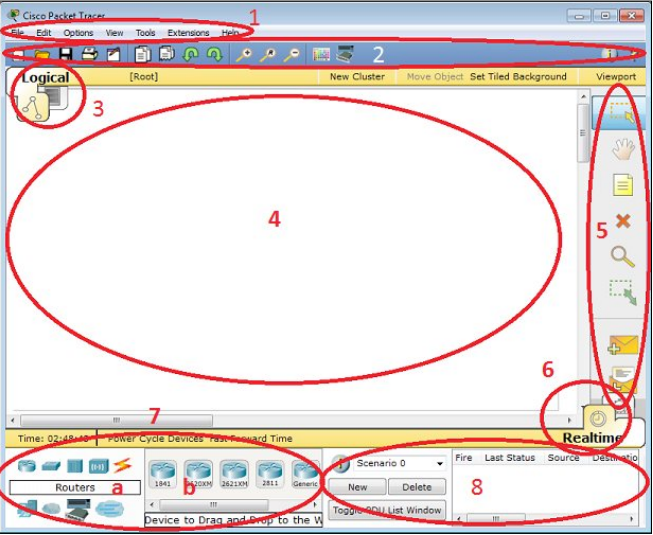
The components of the Packet Tracer interface are as follows:
• Area 1: Menu bar – This is a common menu found in all software applications; it is used to open, save, print, change preferences, and so on.
• Area 2: Main toolbar – This bar provides shortcut icons to menu options that are commonly accessed, such as open, save, zoom, undo, and redo, and on the right-hand side is an icon for entering network information for the current network.
• Area 3: Logical/Physical workspace tabs – These tabs allow you to toggle between the Logical and Physical work areas.
• Area 4: Workspace – This is the area where topologies are created and simulations are displayed.
• Area 5: Common tools bar – This toolbar provides controls for manipulating topologies, such as select, move layout, place note, delete, inspect, resize shape, and add simple/complex PDU.
• Area 6: Realtime/Simulation tabs – These tabs are used to toggle between the real and simulation modes. Buttons are also provided to control the time, and to capture the packets.
• Area 7: Network component box – This component contains all of the network and end devices available with Packet Tracer, and is further divided into two areas:
° Area 7a: Device-type selection box – This area contains device categories
° Area 7b: Device-specific selection box – When a device category is selected, this selection box displays the different device models within that category
• Area 8: User-created packet box – Users can create highly-customized packets to test their topology from this area, and the results are displayed as a list. Make sure you are familiar with these names, because moving forward we will be referring to them frequently
In first Lab we simulate a connection between two pc in CISCO packet tracer and ping one pc using the other pc. We assign unique IP address to each pc.
CONNECTION BETWEEN TWO PC
For PC1
IP Address :-192.168.100.10
Subnet Mask:-255.255.255.0
For PC2
IP Address :-192.168.100.20
Subnet Mask:-255.255.255.0
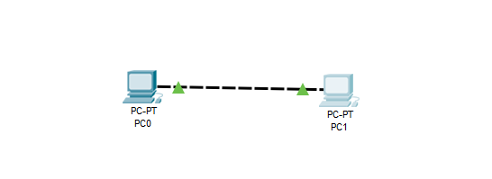
Two PC connected Using Copper Cross-Over Wire
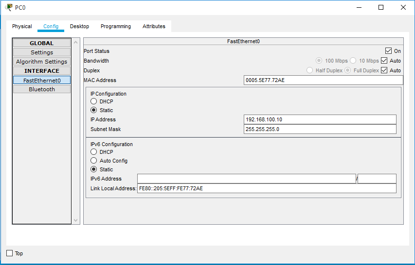
IP Address Settings For PC0
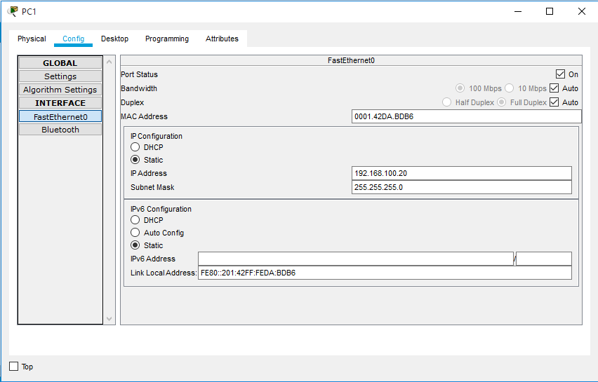
IP Address Settings For PC1
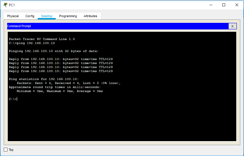
PC0 is pinged using PC1
